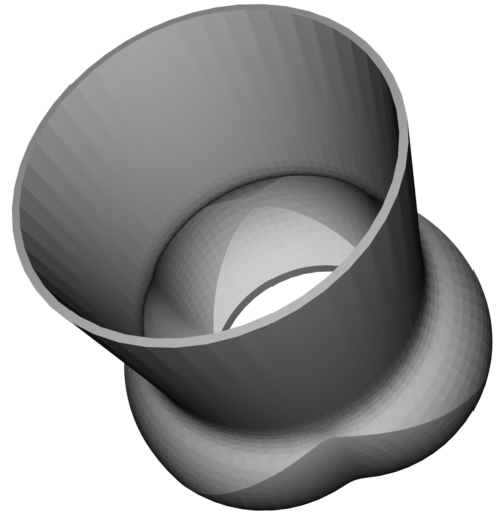
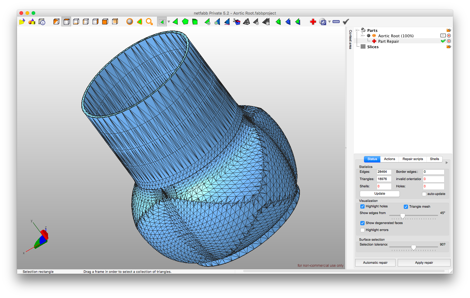
This is just one example of how to prepare a surface mesh for further processing whether it's printing
or subsequent generation of a volume mesh. Here, I'll use a CAD generated geometry of an aortic root. When an STL file
is generated from DICOM files, the process of cleaning/repairing the surface mesh is more laborious.
Analyze and repair the surface (STL) mesh if necessary. Check for: (1) Warpage, i.e. amount by which an element or element face (solid elements) deviates from being planar. It should be less than 15°,
(2) Aspect Ratio, i.e. ratio of the longest edge of an element to its shortest edge. It should be less than 5:1,
(3) Skew should be less than 60°, (4) Jacobian, i.e. measure of the deviation of an element from an ideally shaped element.
It ranges from 0 to 1.0, where 1.0 represents a perfectly shaped element and for a healthy mesh it should be greater than 0.6 for each element.
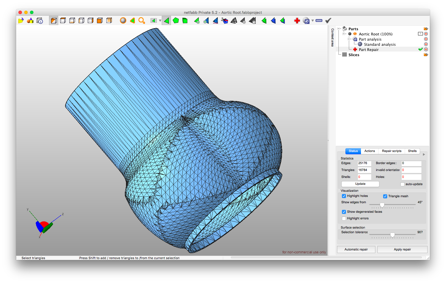
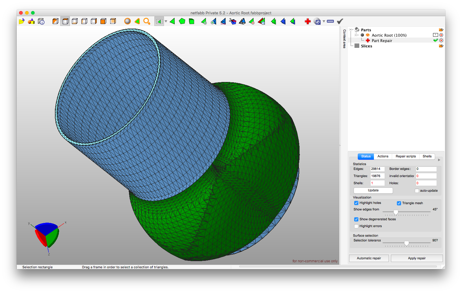
I'm using netfabb Private:
to select all these triangles with bad aspect ratio of the longest edge to the shortest edge
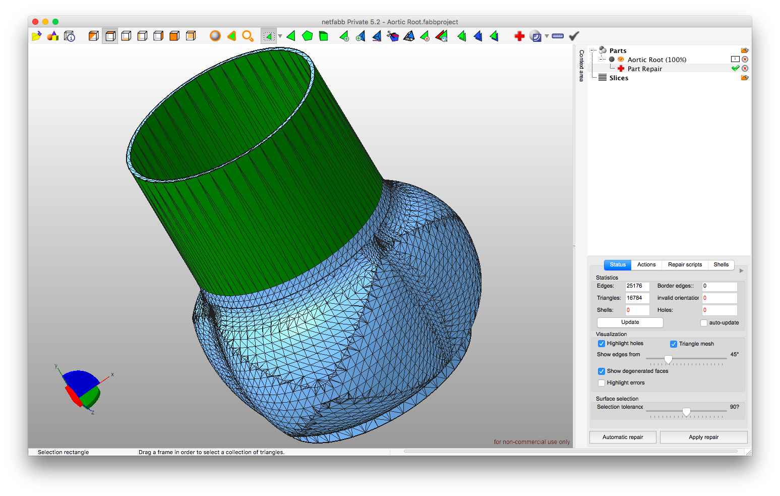
and then refine the selected triangles by defining a new maximum edge length:
resulting in the following:
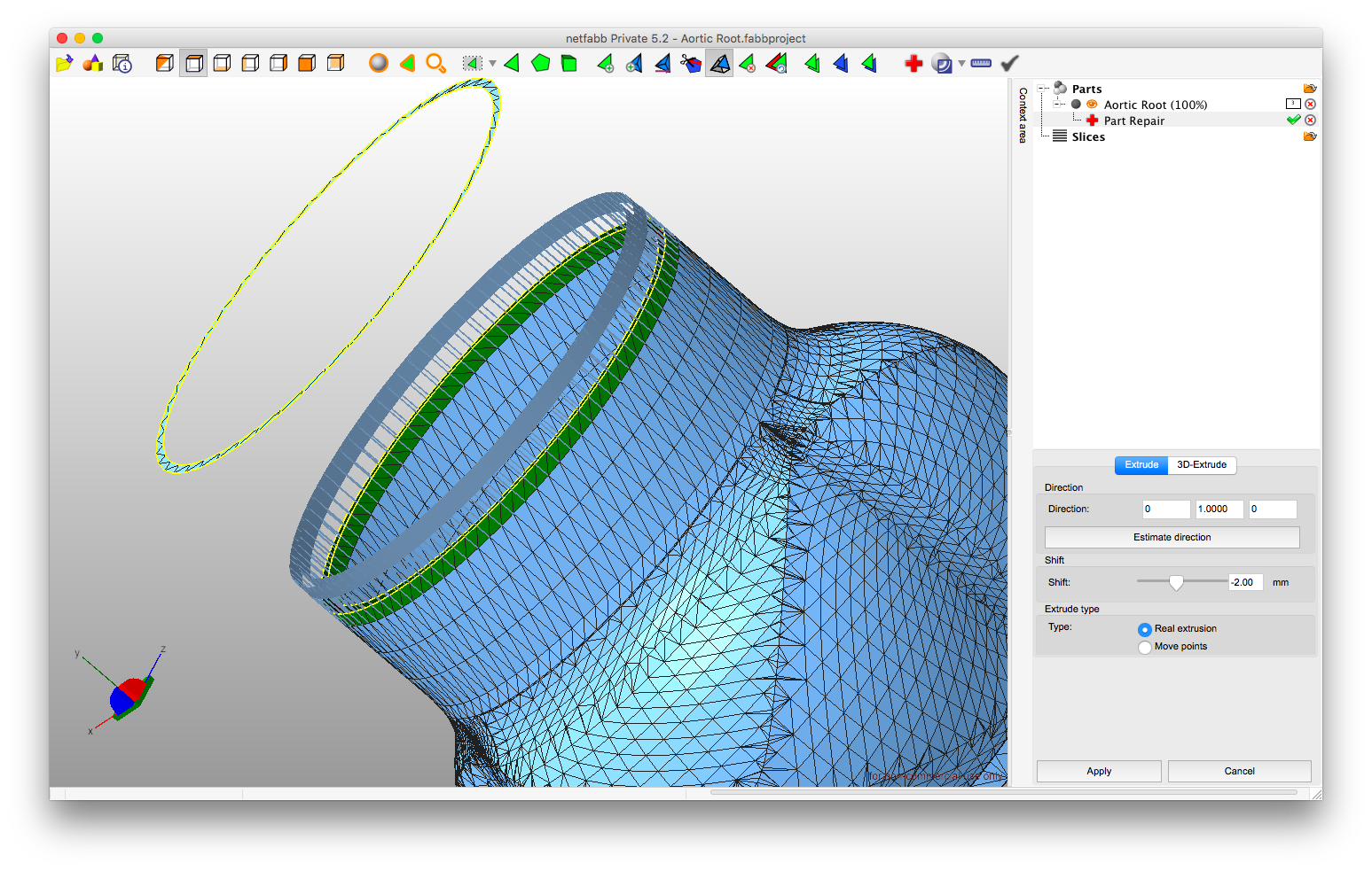
But sometimes the automatic algorithms do no perform the best so here I deleted that part of the surface and recreated it by 'extrude surface' function.
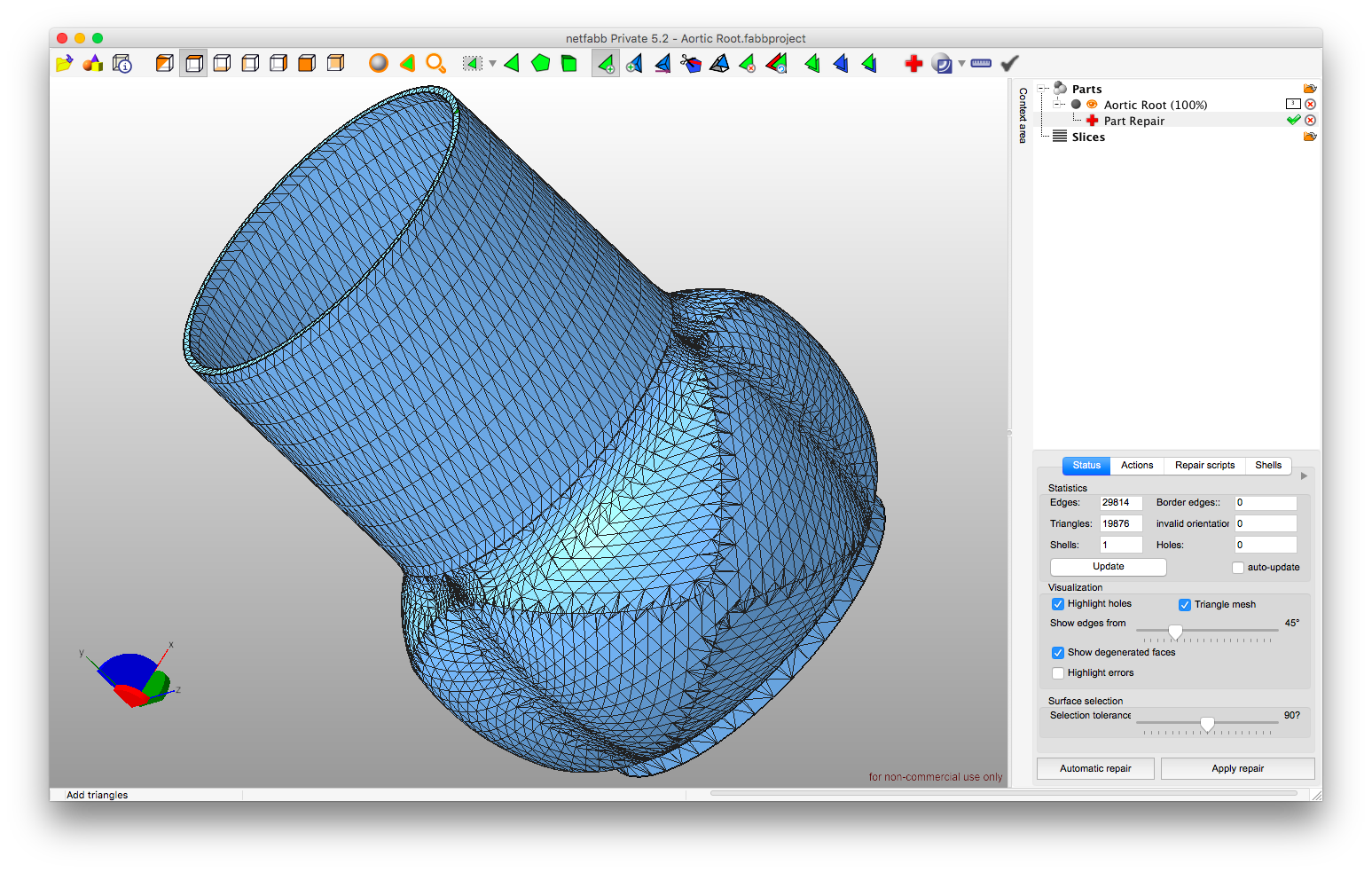
resulting in the following:
But, you can use whatever technique you wish to either recreate the surface, or correct the mesh any other way available. Or, simply keep the one that resulted after the use of the automatic algorithms. Just remember one thing, "prettier" (high quality) surface mesh leads to high quality volume mesh right away.
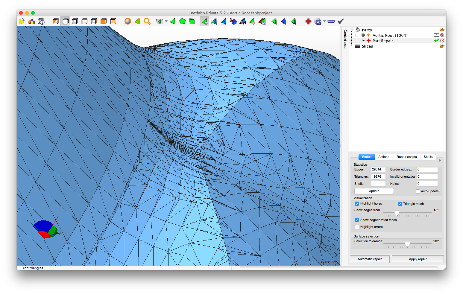
The following zone where I'd prefer the mesh to be of higher quality comes to mind:
You can see too high concentration of triangles for a surface that isn't that uneven and could therefore be created by smaller number of triangles with better distribution. Hence, resulting in higher quality mesh with better aspect ratios.
To reduce the triangles I decided to select the entire zone as shown in the following figure.
Then, I used 'basic triangle reduction' function and chose the 'as low as possible' option:
resulting in this
Now, all these options and functions were chosen after I tried other options too. It won't be the best choice for every geometry and one needs to experiment to find what works the best.
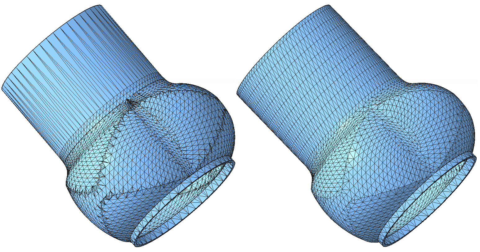
The following is the before and after figure of the original surface mesh and the "pretty" one after all the above steps applied.
The old mesh before repair consists of 16784 triangles and the new mesh consists of 13176 triangles, which is also beneficial.
The minimum and maximum edge lengths are 0 and 16.56 mm for the old mesh, respectively; and, 0.50 and 2.44 mm for the new mesh, respectively.
Even if the minimum and maximum edge lengths belonged to the same element, the 5:1 ratio of the longest edge of an element to its shortest edge would still be satisfied.