

Message
Message
|
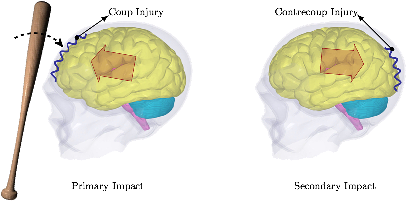
Vancouver, BC, Canada Predicting Concussion Symptoms Using Computer SimulationsOld Westbury Campus - HSH 116A, Northern Boulevard, Old Westbury, New York 11568-8000, USA AbstractThe reported rate of concussion is smaller than the actual rate. Less than half of concussion cases in high school football players is reported. The ultimate concern associated with unreported concussion is increased risk of cumulative effects from recurrent injury. This can, partially, be attributed to the fact that the signs and symptoms of a concussion can be subtle and may not show up immediately. Common symptoms after a concussive traumatic brain injury are headache, amnesia and confusion. Computer simulations, based on the impact force magnitude, location and direction, are able to predict these symptoms and their severity. When patients are aware of what to expect in the coming days after head trauma, they are more likely to report the signs of concussion, which decreases the potential risks of unreported injury. In this work, the first ever fluid-structure interaction analysis is used to simulate the interaction between cerebrospinal fluid and comprehensive brain model to assess the concussion symptoms when exposed to head trauma conditions.I. IntroductionIn 1981, Goldsmith's letter to the editor states, "The state of knowledge concerning trauma of the human head is so scant that the community cannot agree on new and improved criteria even though it is generally admitted that present designations are not satisfactory" [1]. Even decades later, this assessment can still be considered reasonable to a degree.The head model presented here is the only model currently incorporating cerebrospinal fluid (CSF) flow. Other reported head models treat CSF as a solid part incapable of flowing around the brain when exposed to head trauma conditions [2-6]. The CSF flows even on its own when the head is at rest, albeit slowly. Obviously, when the head is exposed to a sudden stop, e.g. in a car accident, the CSF flow around the brain has a significant contribution to the head injury mechanism. Without the flow the simulated cushioning effect of CSF can not be considered realistic. The most common reasons for concussion not being reported include a player not thinking the injury is serious enough to warrant medical attention (66.4% of unreported injuries), motivation not to be withheld from competition (41.0%), and lack of awareness of probable concussion (36.1%) [7]. Regardless of the reason, as McCrea et al. state, "Future prevention initiatives should focus on education to improve athlete awareness of the signs of concussion and potential risks of unreported injury.", [7]. Needless to say, there is an unlimited number of trauma situations that can occur, and the concussion symptoms can vary from one case to another. In some cases, the skull is dented inward and it presses against the surface of the brain. These types of fractures occur in 11% of severe head injuries. In impact sports, the skull dentation rarely occurs. Most sport-related brain injuries result from coup-contrecoup type of injury. Coup-contrecoup injury is dual impacting of the brain into the skull; coup injury occurs at the point of impact; countercoup injury occurs on the opposite side of impact, as the brain rebounds, see Fig. 1. Most common causes of coup-contrecoup brain injury include circumstances when the head jerks violently, e.g. during motor vehicle accidents, when baseball players are colliding during the chase for a ball, football players tackling, boxers punching, and so on.
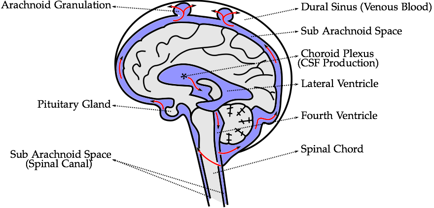
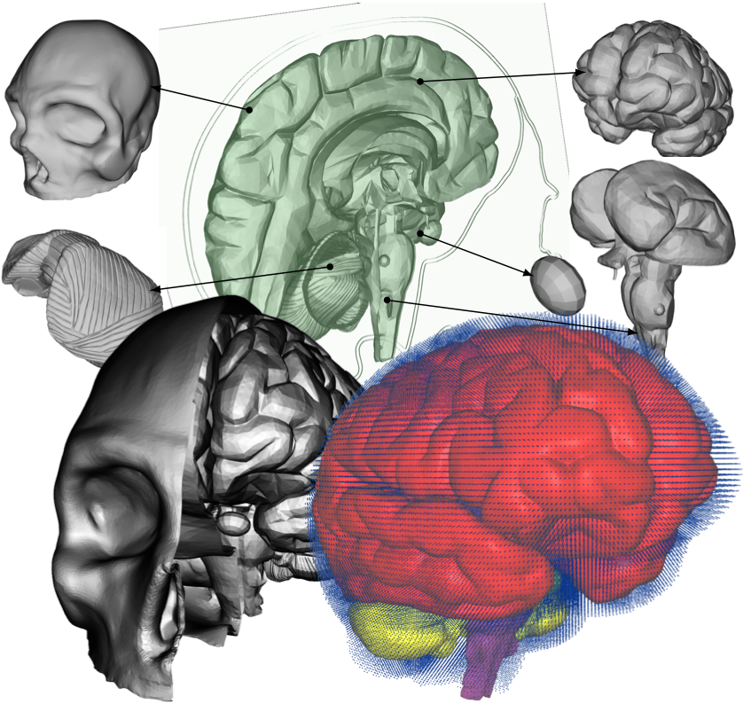
II. MethodsThe methods section describes the creation of the head model, loading conditions used for its validation, and numerical and computational methods used.A. Head ModelThe five distinct anatomical structures used in this model are shown in Fig. 3. The skull, cerebrum, cerebellum, pituitary gland, and brainstem each have unique material properties. The patient-specific model is based on the Digital Imaging and Communications in Medicine (DICOM) images acquired from an online database. Anatomical features missing in this model include the skin, spinal cord, meninges, and the arachnoid granulation, Fig. 2. When compared to the very short impact impulse time history used in these simulations, the CSF flow in the head can be neglected, too. The CSF flow is relatively slow, 0.05 - 0.08 m·s-1, i.e. during the impact impulse time history the CSF flows by 0.2 - 0.3 mm. These assumptions also make the presence of the granulations negligible.
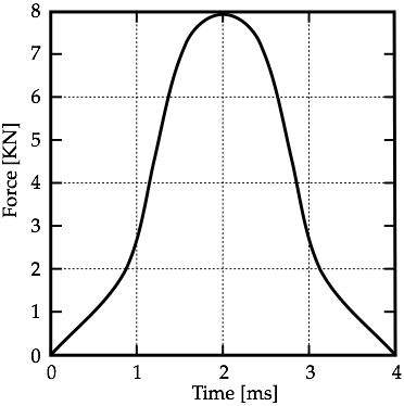
B. Loading ConditionsBased on whether the head is stationary and struck by a moving object, or is moving and strikes a stationary object, the type of brain injury differs, according to [10]. The stationary head is usually hit by objects which are of similar mass to the head. In this study, the scenario in Fig. 1 is used and it is assumed that the impacting object does not penetrate the skull. Thus, local deformation of the skull in the frontal area is not resulting in direct contact injury to the underlying brain tissue. It has been estimated that for a contact area of approximately 6.5 cm2 the force required to produce a clinically significant skull fracture in the frontal area of the cadaver skull is twice that required in the temporoparietal area [11].Corresponding loading conditions from cadaveric experiments in [12] are used to perform the computational analysis of a frontal impact. The experiments examined the blow to the head of a seated human cadaver. The impact pulse history applied to the skull of the computational model is shown in Fig. 4.
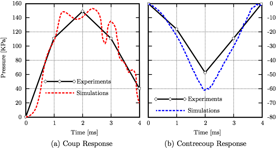
C. Computer SimulationsThe model is comprised of 5 parts. The skull part is assigned rigid material properties with density 1900 kg·m-3 [13]. Data from studies characterizing the macroscopic physical characteristics of the brain show that it is a viscoelastic material [14]. The cerebrum, cerebellum, pituitary gland, and brainstem are simulated using a non-linear elastic constitutive material model with varying material properties based from the literature [15-19]. The cerebrum, cerebellum, brainstem, and pituitary gland are each composed of a different number of tetrahedral elements; 96385, 40808, 18634, 310, respectively. The CSF is modeled using the smoothed-particle hydrodynamics (SPH) method with the bulk modulus of 21.9 GPa [3] and density 1000 kg·m-3 [20]. The number of fluid particles filling the subarachnoid space between the skull and brain, and other cavities, is 94,690.Fluid motion and boundary interaction calculations were solved with the IMPETUS Afea SPH Solver® (IMPETUS Afea AS, Norway), while large deformations in the solid parts were simultaneously solved with the IMPETUS Afea Solver®. Both the solvers use a commodity GPU for parallel processing. All solid elements were fully integrated, removing the possibility of hourglass modes and element inversion that plagues the classic under-integrated elements. Both fluid and solid domains and their interaction were solved with an explicit integration scheme. All simulations were solved on a standard workstation. Parallel acceleration is achieved with a Tesla K40 GPU with 12 GB of Graphic DDR memory and 2880 CUDA Cores. To confirm that convergence is reached, h-refinement of the finite element mesh is performed, and the solution is found to yield same results. Similarly, smaller number of fluid particles is used to obtain results within 5% of the values obtained with the higher number of particles. The above stated number of particles, 94,690, is high considering that the volume of the cavities and subarachnoid space is much smaller than rest of the model. This confirmed that the results are converged. Our prior publication describes the SPH equations in greater detail [21]. The SPH method is chosen for this study because traditional FSI techniques can be computationally expensive and challenging regarding their parallelization [22]. In order to use traditional FSI techniques, geometrical simplifications would need to occur, and the anatomical accuracy would have to be sacrificed. Moreover, in recent years the SPH has been increasingly used in biomedical applications [23]. III. ResultsThe results section shows validation of the simulations matching coup and contrecoup responses in CSF with experimental results. The stress values on the cerebrum resulting from the frontal impact are shown and SPH impulse intensity is superimposed with the Boadmann's map of cytoarchitectonics.A. ValidationThe loading conditions from cadaveric experiments (Fig. 4) applied to the frontal lobe yield corresponding coup and contrecoup pressure responses in CSF, see Fig. 5 where both experimental [12] and computational results are shown for comparison.
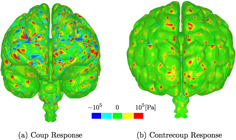
B. Second Deviatoric Principal StressThe stress values on the cerebrum resulting from the frontal impact are shown in Fig. 6. The stress maxima can be found also on the occipital lobe which supports the experimental observations that forehead injury can result in additional injury to occipital area. Similar conclusion, i.e. stresses and strains seen in both frontal and occipital lobes, is also found in other more simplified computational studies, e.g [5].
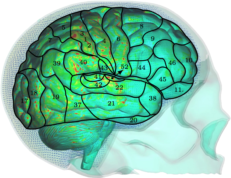
C. SPH impulse intensityThe typical variables used in biomedical fluid mechanics, such as wall shear stress, are challenging to derive using SPH. However, SPH does provide different variables with similar meanings. For example, SPH impulse intensity, which is SPH driven mechanical impulse per unit area in pascal-second, can be interpreted as wall shear stress.Fig. 8 show the SPH impulse intensity at peak impact impulse [26]. The SPH impulse intensity develops slowly at first, but reaches its maximum values around the peak. The parietal and upper temporal lobes are the most affected by the fluid particles during their migration to the occipital/parietal bones, i.e. the acceleration phase. At the peak when the fluid particles change direction and start their migration towards the frontal bone, the high SPH impulse intensity values are more visible also in the occipital lobe.
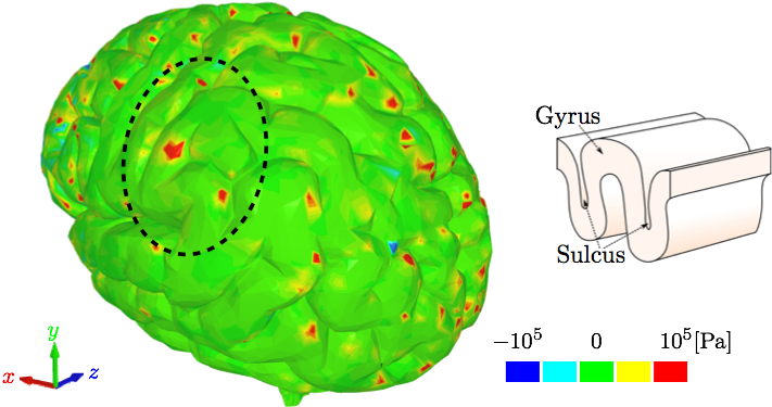
IV. DiscussionThe different layers of the brain move at different times because each layer has a different density. Simplified computational models are not able to incorporate this important aspect. Moreover, interaction between CSF and brain gyri and sulci can not be analyzed computationally if the methods used do not model the CSF as fluid. The model used in this study uses a comprehensive head/brain model with detailed representation of all the parts and the computational analysis used is an FSI method with fluid properties for the CSF. The validation of this model and the computational method is shown comparing the coup and contrecoup pressure responses in CSF with the experimental results from cadaveric experiments.The anatomical features missing in the head model include the skin, arachnoid granulations, spinal cord, vasculature, and meninges. Skin is irrelevant for our objectives. The arachnoid granulations are negligible due to the relatively slow CSF flow. To make the simulation less computationally expensive, the spinal cord, vasculature, and meninges are omitted at this stage but may be considered in future studies. In Fig. 5, where coup and contrecoup pressure responses in CSF compared to the experimental results of [12] are shown, it can be observed that the agreement with the experimental results is better in the coup response as opposed to that in the contrecoup response. The contrecoup pressure response reaches slightly higher values compared to the experimental data because the contrecoup response is secondary and therefore more dependent on the patient-specific geometry used. However, both coup and contrecoup computational pressure responses can be considered of good agreement with the experimental measurements. As discussed, if the interaction of CSF with the brain is to be analyzed the CSF has to be modeled with fluid elements or particles and not just with fluid-like solid elements. The results then have potential to show more complex responses to the loading conditions. For example, Fig. 6 shows that the contrecoup stress response is prevalent mostly in the inner areas of the two hemispheres close to the edges where longitudinal fissure separates the two halves of the brain. The brain model is comprehensive containing multiple parts each with detailed realistic patient-specific geometry. The complexity of the model enables the analysis of the brain down to the exact gyrus and sulcus. Additional areas of high stress values can be found outside the frontal and occipital lobes. However, interestingly, only the posterior aspect of the gyrus seems to be affected. This can be explained by following the wave in the CSF that occurs after the impact to the frontal lobe [26]. During the acceleration phase when the brain wants to move backwards relative to the skull the fluid particles move to concentrate in the space between the skull and occipital lobe to provide the cushioning effect and prevent the brain from impacting to the skull. At that point the moving particles affect mostly the anterior sides of the gyri. When the brain rebounds and wants to move forward relative to the skull the fluid particles move to the space between the skull and frontal lobe to provide the cushioning effect there. At that point the moving particles affect mostly the posterior side of the gyri. Other parts of the brain, such as the brain stem, are equally affected by the coup-contrecoup injury. The variables commonly used to post-process the results in the biomedical fluid mechanics are somewhat different from those readily available in the SPH method. Extracting wall shear stress values from SPH method is more challenging than when using traditional FSI techniques. However, there are other variables that can be used and offer similar meaning, such as the SPH impulse intensity. SPH is used in this study to maintain as much anatomical accuracy as possible. Traditional FSI techniques would require more anatomical simplifications. Fig. 8 shows the cortical areas affected by the SPH impulse intensity at the peak [26,27]. The diffuse pattern of SPH impulse intensity maxima may represent the cortical areas most affected by a concussion. Brodmann's areas with at least 10% coverage of maximal SPH impulse intensity include 40 (10.1%), 4 (11.7%), 1,2,3 (15.3%) and 52 (21.7%). Brodmann area 40, the left supramarginal gyrus, receives input from multiple sensory modalities and supports complex linguistic processes. Lesions here may result Gerstmann syndrome and fluent aphasia, such as Wernicke's aphasia. Brodmann area 4 is typically associated with motor functions but also plays a supportive role in sensory perception. Lesions in the primary motor cortex may result in paralysis and decreased somatic sensation. Brodmann areas 1,2, and 3 comprise the postcentral gyrus in the parietal lobe and are primarily associated with somatosensory perception. Lesions in the postcentral gyrus may result in cortical sensory impairments, including loss of fine touch and proprioception. Brodmann area 52, the parainsular, is the smallest of the mentioned areas and has the high percentage of SPH impulse intensity maxima coverage. It joins the insula and the temporal lobe. This validated model, where an FSI method is used to analyze the interaction between CSF and brain, is a step closer to understanding the mechanisms of brain injuries. Concussions are typically diagnosed symptomatically. Patients may exhibit a range of symptoms, such as headache, photophobia, tinnitus, dizziness, sleepiness, confusion, and behavioral changes. Different area of brain affected would potentially result in different set of symptoms. The model and method presented in this study can predict the areas affected based on the loading conditions. Therefore, the symptoms can be predicted, too. Since the signs and symptoms of a concussion can be subtle and may not show up immediately, a numerical analysis of this kind could serve as a predictor for the physicians and patients who then could be warned about what symptoms they are to expect and be ready for. Hence, if used in practice, it has the potential to contribute to early diagnosis which is important in treatment of concussion.
|
Contact Us
Phone
+1-516-686-3765
Address
Dept. of Osteopathic Manipulative Medicine
College of Osteopathic Medicine
New York Institute of Technology
Serota Academic Center, room 138
Northern Boulevard, P.O. Box 8000
Old Westbury, NY 11568
mtoma@nyit.edu